Technical Guide - Infield Verification following ASTM E83 -23
Setup
Set-up, plug-in, and power-on the Vector.
Confirm Vector enters scanning, with an oscillating blue light.Confirm Vector connects to the Interface App.Mount the Vector infront of the verification device.
Ensure the verification device is positioned securely, the Vector is mounted suitably, and the distance between the instruments is within specification.For more information, see sections Mounting, Connections, and Installation and Positioning Vector of the User Manual.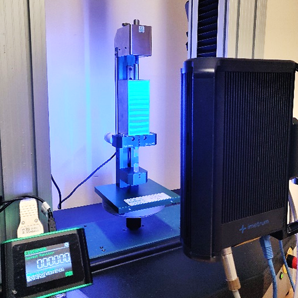
Information - transverse verifications

Allow Vector to acclimatise to the laboratory environment and temperature.
Ensure Vector is powered ON and in scanning mode for a recommended 20 minutes.Configure the measurement type and units.
Measurement and Units are set within the Interface App - Settings: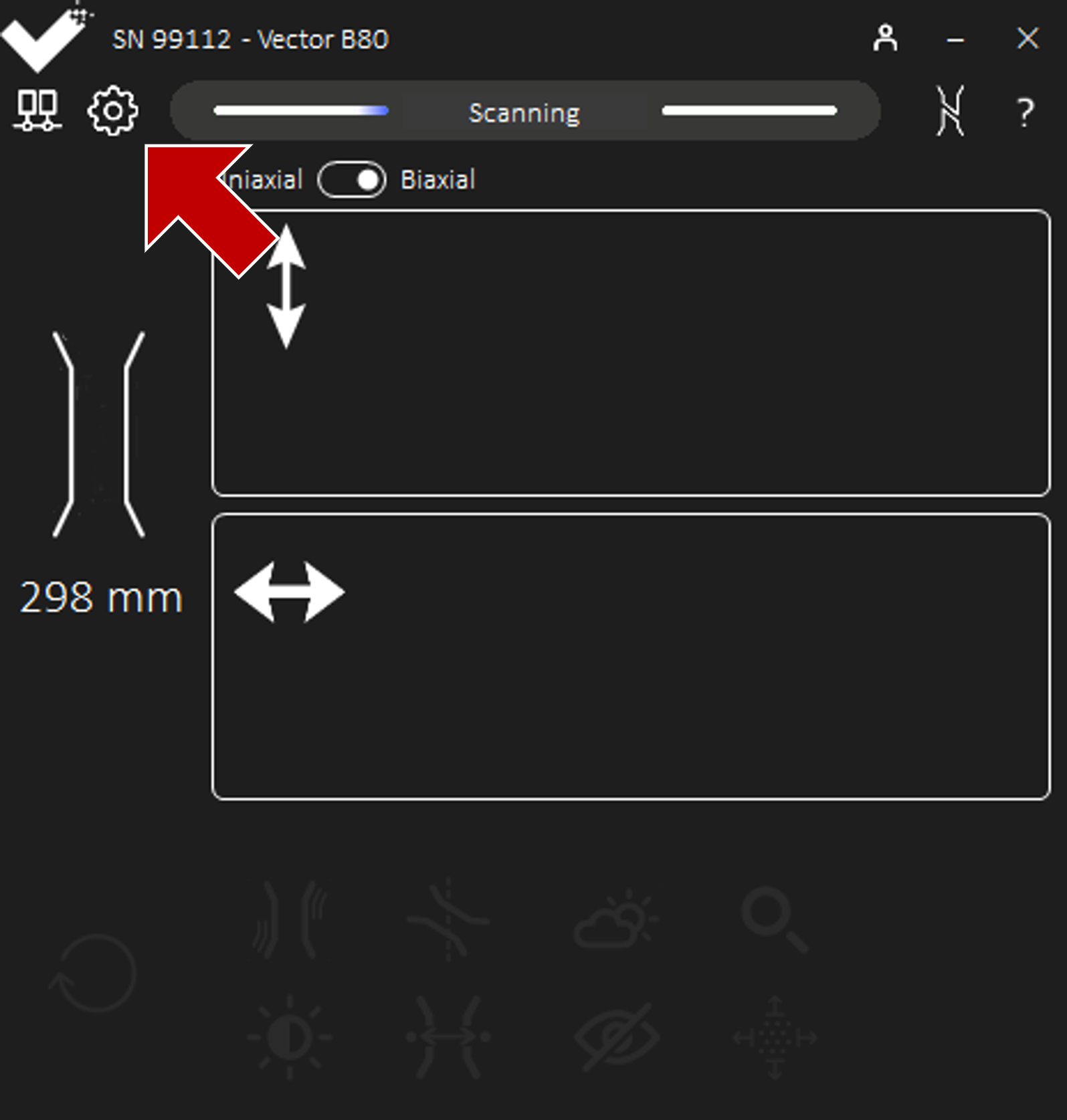 If extension or elongation is required for verification (for example, deflection ISO 5893), configure the measurement type as extension.
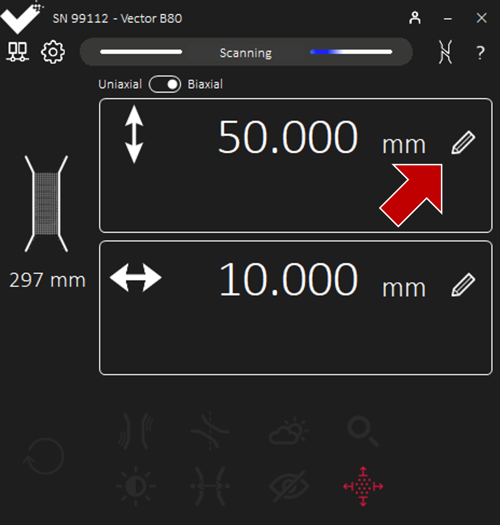
 If calibrating transverse, set Vector to Biaxial in the Interface App - Settings.
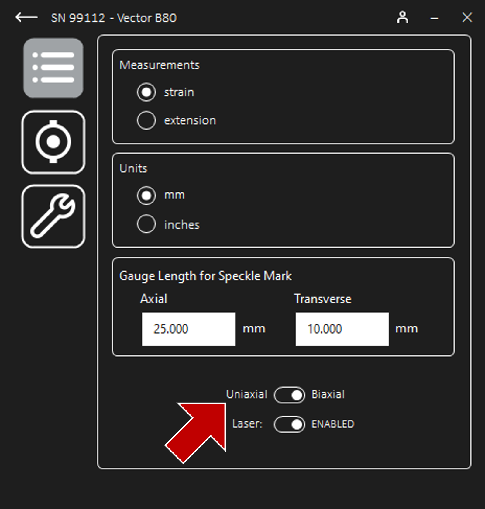
Configure the measurement output.
Analogue scaling is configured within the Interface App - Settings - Output.Confirm the scaling is correct for both the Vector and UTM using the set output options.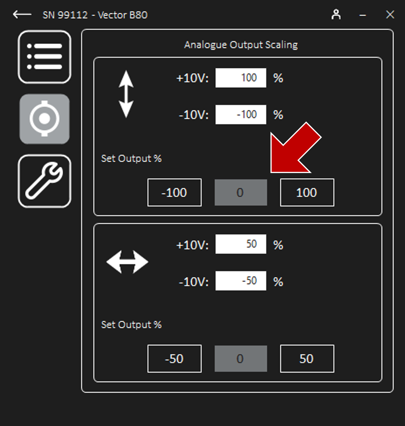 For more information, see Scaling the Analogue Output Signal of the User Manual.If calibrating transverse, confirm the scaling is correct for the transverse channel in the same way.
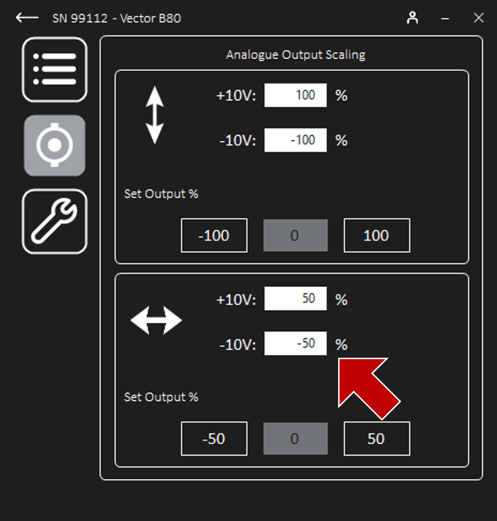
Information - digital output
Information - analogue output
Inspection
- Inspect the optical windows on the front of the Vector for scratches, smears, dust, or debris.
- Note the initial condition is “As Found”.If verifications are reattempted, clean the front of Vector with a clean microfibre cloth.
- Inspect the condition of the power and data cables for damage, especially the analogue connection.
- Confirm that the recieved analogue signal at the UTM is not affected by movement of the data cables.If noise is present, change the cables.
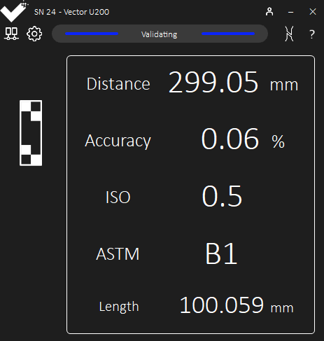
- Inspect the reported class in the Interface app when using the validation block provided.
- Confirm the class is B-1 throughout the rated field of view.If lower classes are shown consistently in the field of view, contact your supplier.
Gauge length
Rationale
Marking and positioning verification device spindles
When Calibrating Axial
Mark the spindles.
Clean, prepare and mark the spindle blocks in a similar way that will be employed for specimen testing.For more information, see Specimen Marking of the User Manual.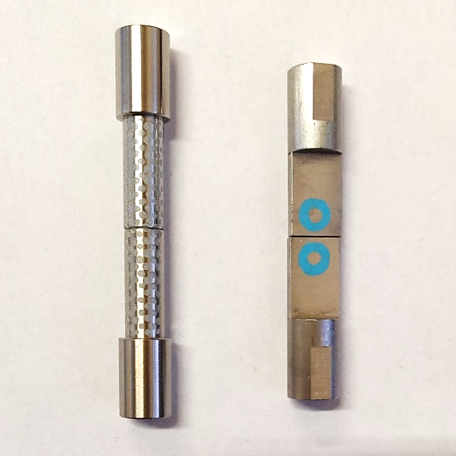
Position spindles to represent the specimen.
Ensure spindles are square and aligned.For rings and filled circles, space the spindles accordingly to represent the gauge.For speckled spindles, ensure the spindles are mounted closely together to form a single, contiguous speckle region.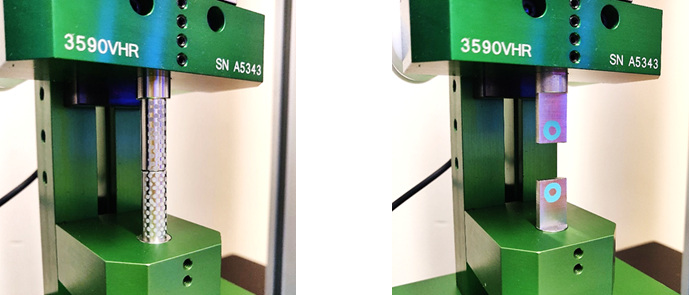
Mount the Vector infront of the verification device.
Ensure the verification device is positioned securely, the Vector is mounted suitably, and the distance between the instruments is within specification.For more information, see sections Mounting, Connections, and Installation and Positioning Vector of the User Manual.
When Calibrating Transverse
Mark the spindles.
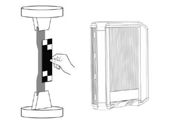
For transverse, the verification process is performed with the extensometer perpendicular to the verification device. Specific spindles are required to calibrate the transverse.Clean, prepare and mark the spindle blocks in a similar way that will be employed for specimen testing.For more information, see Specimen Marking of the User Manual.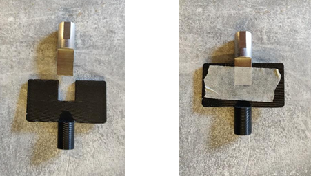 The example shown is for a 3590VHR, using a standard flat spindle and a custom transverse “paddle”. Alternative custom paddles may be required for other verification devices.For convenience, tape the flat spindle and paddle together so that the spindle end and the paddle are almost touching. This is the spindle gap and the centre line of the setup.
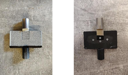 On the other side, mark the setup with appropriate markings for the verification. As the axial measurement is required but untested, the gauge length is not relevant.Ensure that the markings are symmetric about the centre line of the setup; i.e. ensure that the marking length is vertically centred to the spindle gap.
Position spindles to represent the specimen.
Ensure the paddle is connected to the fixed head of the verification device.Ensure spindles are square and aligned.For rings and filled circles, space the spindles accordingly to represent the gauge.For speckled spindles, ensure the spindles are mounted closely together to form a single, contiguous speckle region.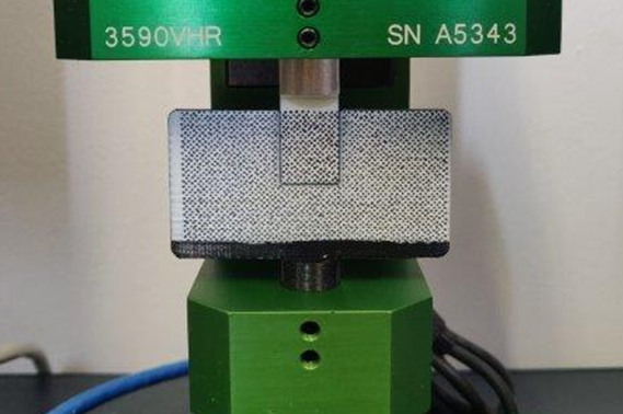
Mount the Vector infront of the verification device.
Ensure the verification device is positioned securely, the Vector is mounted suitably, and the distance between the instruments is within specification.Position Vector horizontally, either by using the dedicated “landscape orientation intermediary” or by rotating the extension arm extrusion a quarter turn and reinserting into the extension arm housing.For more information, see sections Mounting, Connections, and Installation and Positioning Vector of the User Manual.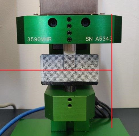 Ensure that the central laser passes through the spindle gap. Ensure that the bottom laser is just outside the edge of the paddle, such that both axial and transverse measurements are performed.
Information - transverse verifications
Verification process
Position the Vector at the correct distance from the verification device.
Adjust, measure, and record the distance between the front face of Vector and the front face of the verification device blocks. Refer to the user manual for operating limits.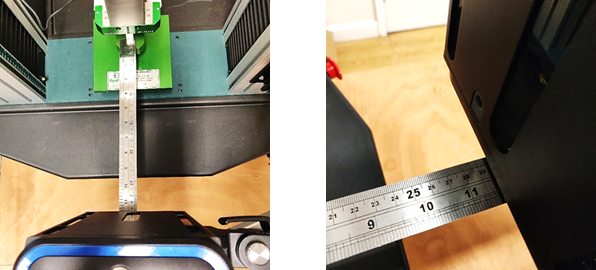 Alternatively to a ruler, the Vector reports the distance to markings and validation block within the Vector Interface App.
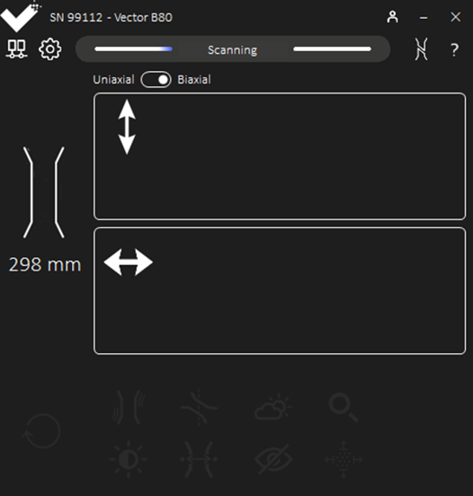
Align the Vector to the spindles using the laser alignment guides.
Ensure:The central laser aligns with the central travel of the verification device.
The lower laser is just below the markings.
Ensure the mounting is secured and the locking levers are firm. For more information, see section Positioning Vector of the User Manual.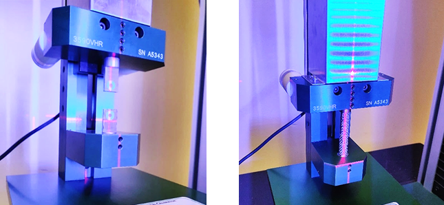
Prevent any Obstructions or Vibrations.
Ensure the Vector is not obstructed during a verification, including any blockage to the lights.Ensure the Vector and verification device are securely mounted and in a still environment.If required, allow the system to settle for a second after each motion.
Preperation Before Each Verification Run
Zero Vector Before Each Run
Reset Vector with a “handstop”.Cover the markings for atleast 1 second to reset Vector.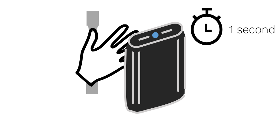 The status lights on Vector will go from green to oscilliting blue to indicate Vector has stopped measuring.Alternatively, the “hand-stop” (Vector Reset) button in the interface can be used.
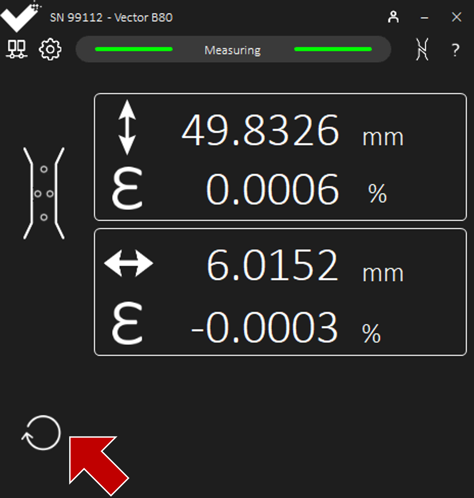
Record the Initial Gauge Length
Ensure Vector is in measuring mode, signified by a solid green light.Ensure the gauge length is as intended.When using speckles, ensure the target gauge length is specified via Options or using the Edit on the Scanning page.
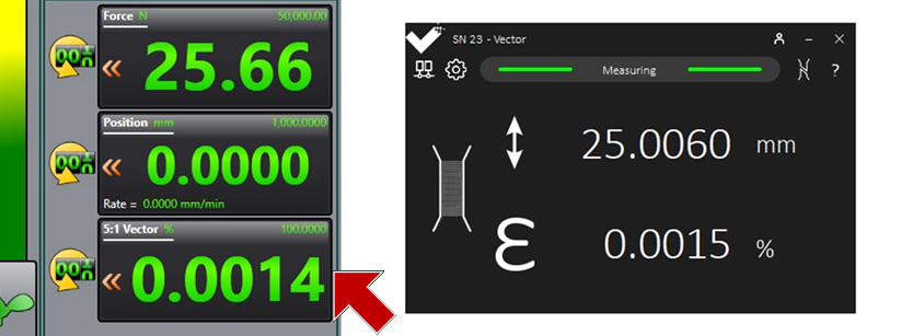
 Refer to the Vector Interface dashboard to help diagnose issues.For each run, record the initial gauge length precisely as that listed by the Vector Interface.
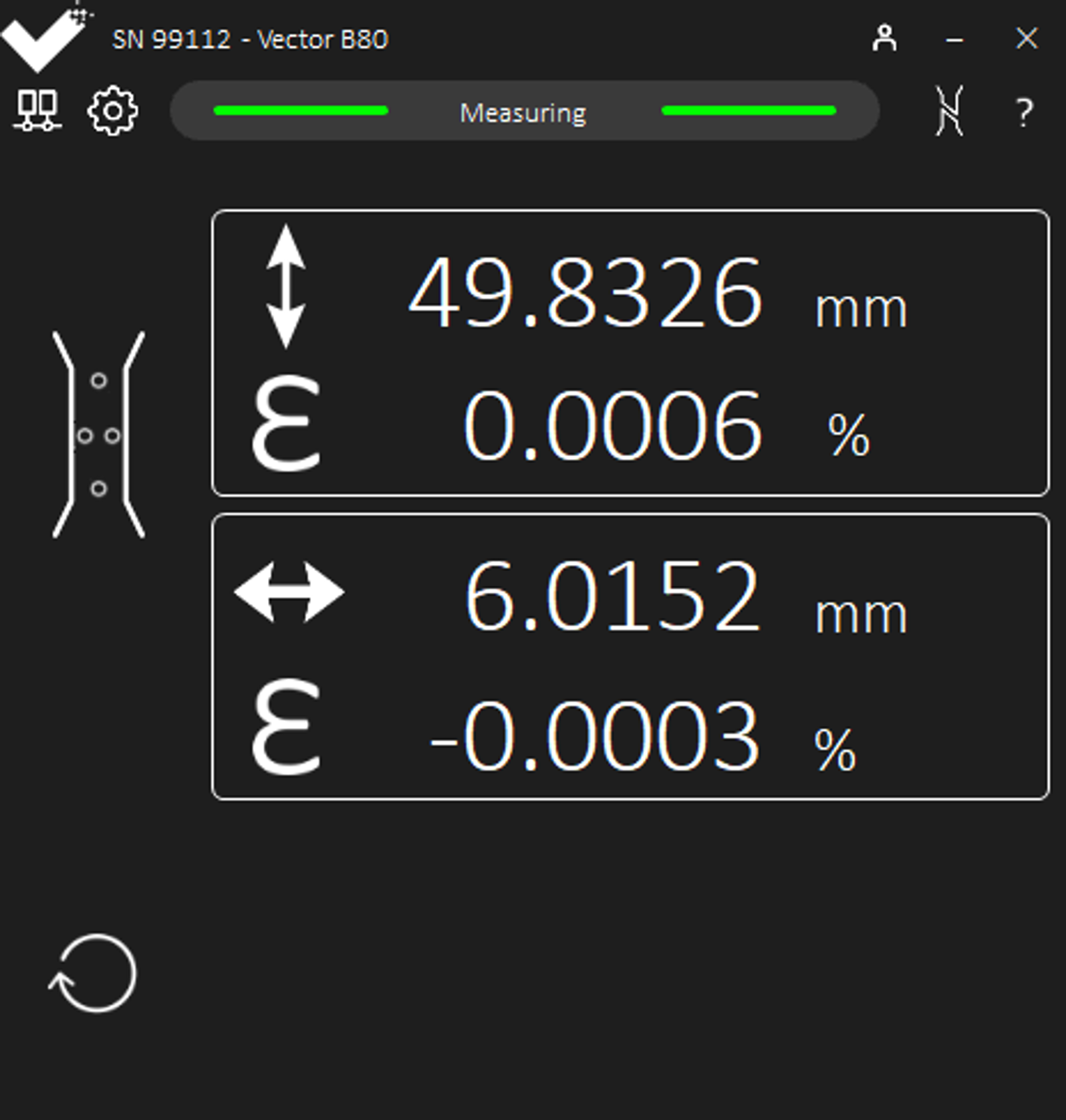
- Take Readings from the System Output
- When using an analogue connection, take readings of the strain and extension from the UTM and test control software.When using a digital connection, the Interface App can be used if more convenient as the values will be identical.