Measurement Output
Scaling the Analogue Output Signal
Vector outputs the measurement as an analogue voltage via a BNC connection. The scaling of the voltage is required when utilising this output and can be configured whenever Vector is Scanning.
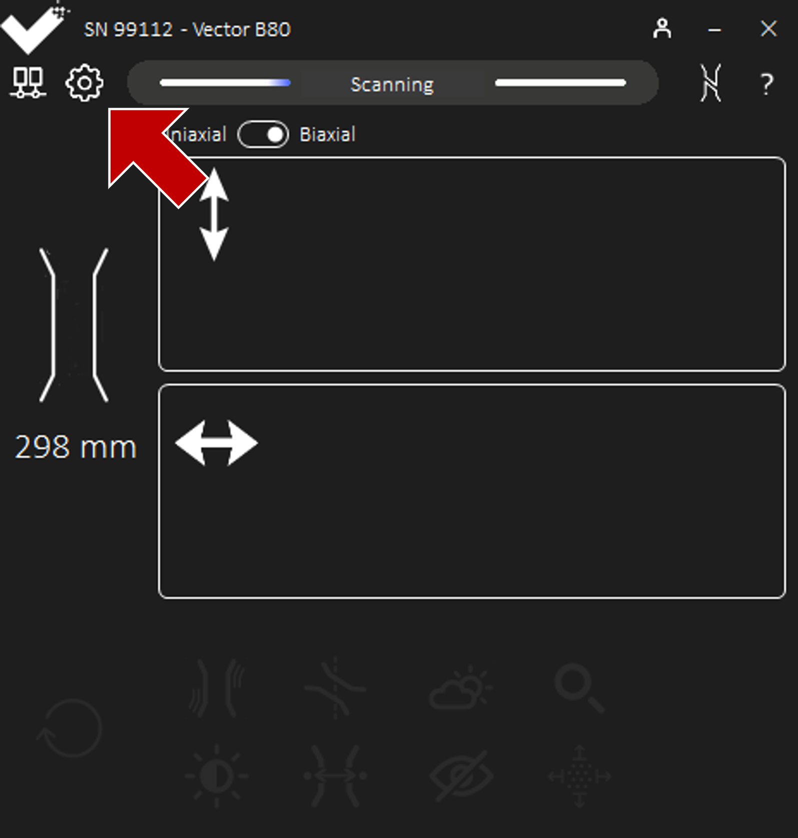
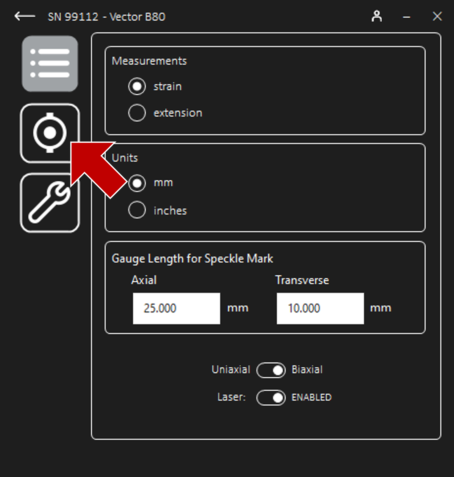
Once connected to Vector, navigate to Settings and then Analogue Output to scale or set the output voltage.
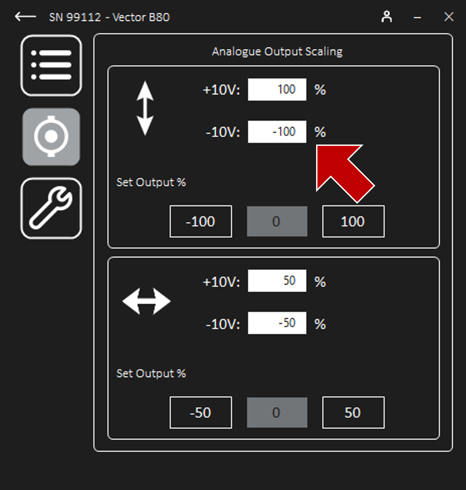
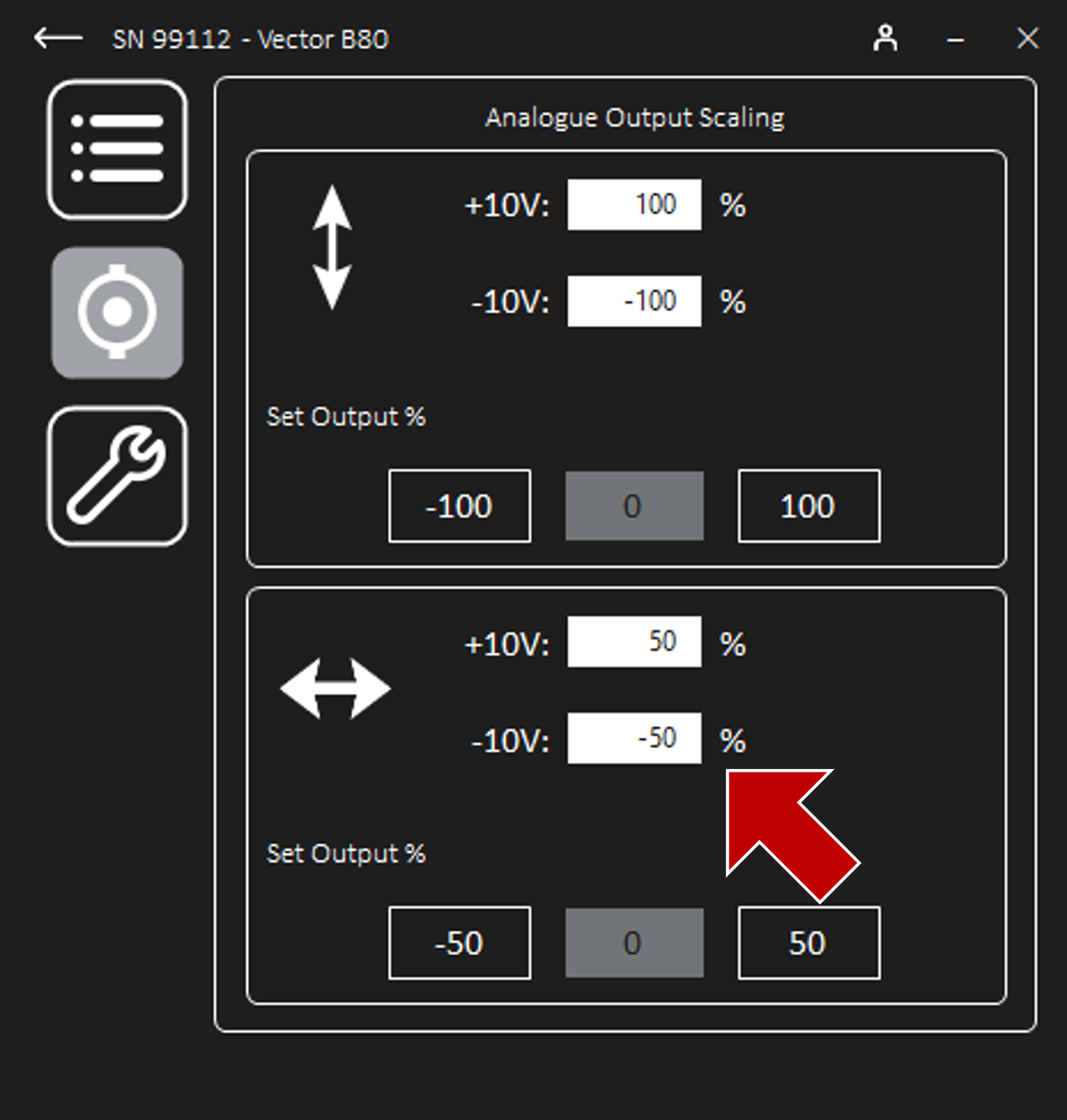
To scale the maximum (+10V) and minimum (-10V) voltages to the desired strain or extension range, input the measurement limits against the corresponding voltages.
To set the output to a fixed value of the minimum, zero, or maximum scale, click on the corresponding Set Output buttons.
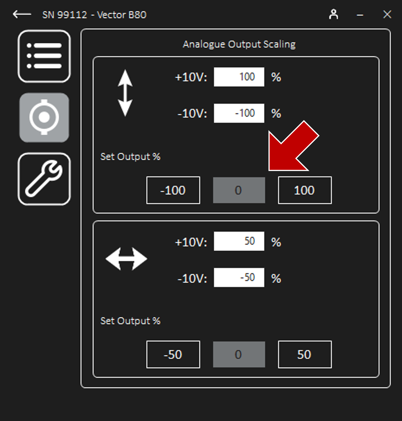
Setting the output is a convenient method during the voltage scaling calibration process, and as a quick check to validate the scale is correct.
Vector B80 has analogue scales for both axial and transverse gauges.
Information - digital output

When using a digital connection
Scaling is not required when using digital. The analogue scaling has no effect on the digital output.
Information - B80
When using Vector B80 only:
Vector B80 has output scaling for both *axial* and *transverse* gauges. The transverse output scaling is visible when Vector is in biaxial mode.
Configuring the Digital Output Signal
Vector can output the measurement as a digital serial protocol via the 15 pin D-sub connector. The desired protocol and it’s parameters can be configured whenever Vector is Scanning.
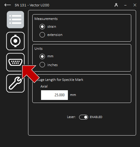
Once connected to Vector, navigate to Settings and then Digital Output to configure the output.
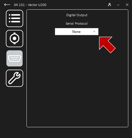
Select the desired protocol from the drop-down box.
The available protocols are listed in the dropdown box. Depending on the selected protocol, additional parameters are listed. It is crucial to ensure parameters on both ends of the serial connection match. Ensure the connection is correct.
Information - digital output
When using a digital connection
Scaling is not required when using digital. The analogue scaling has no effect on the digital output.
Information - digital output
When using a digital connection
Ensure all protocol parameters match on both ends of the connection.
Tinius Olsen Digital Protocol
Vector can output via the Tinius Olsen protocol using the proprietary adaptor cable:
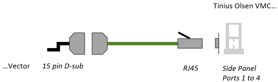
Connect the male 15 pin D-sub to the the female D-sub tail of the Vector Combined Power and Data Cable.
Connect the male RJ45 to an available port on the UTM panel.
Set up the connection and select the Tinius Olsen protocol from the drop-down list.
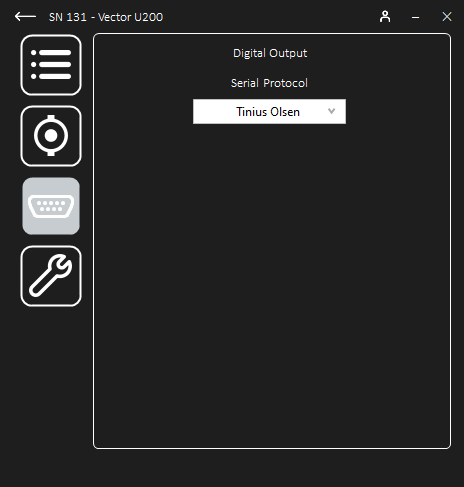
The protocol parameters are automatically set. No further configuration is required in the Interface App.
The UTM will beep to confirm that the connection has been established.
For complete guidance, including the steps to configure the UTM and Horizon for digital, see section Technical Guide - Tinius Olsen Digital Protocol.
Doli Digital Protocol
Vector can output via the Doli protocol using the proprietary adaptor, “Vector Digital Adaptor RS232 Over 9 Pin D-sub”, and a supplied standard 9 pin D-sub straight-through cable:
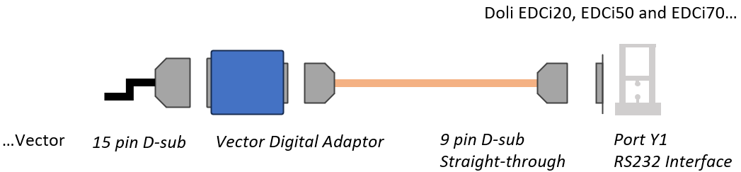
Connect the adaptor male 15 pin D-sub to the female D-sub tail of the Vector Combined Power and Data Cable.
Connect the adaptor male 9 pin D-sub to the female 9 pin D-sub of the standard straight-through cable.
Connect the straight-through cable 9 pin D-sub to the Y1 port of the Doli Controller.
Set up the connection and select the Doli protocol from the drop-down list.
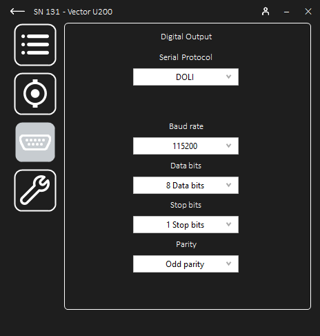
The protocol parameters must match those configured on the Doli controller. Recommended settings are listed below.
For complete guidance, including the steps to configure the UTM and DOLI Hardware Installation Centre for digital, see section Technical Guide - Doli Digital Protocol.
Parameter
Recommended Setting
Baud rate
115200 (maximum)
Data bits
8
Stop bits
1
Parity
Odd