Technical Guide - Doli Digital Protocol
Hardware Set-up
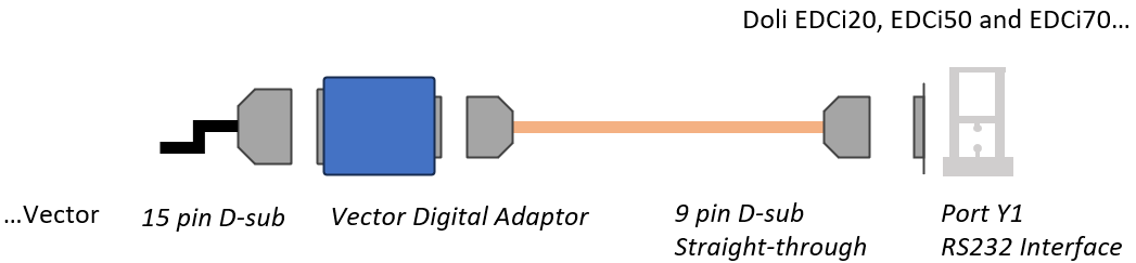
Connect the adaptor male 15 pin D-sub to the female D-sub tail of the Vector Combined Power and Data Cable.
Connect the adaptor male 9 pin D-sub to the female 9 pin D-sub of the standard straight-through cable.
Connect the straight-through cable 9 pin D-sub to the Y1 port of the Doli Controller.
Vector Interface Configuration
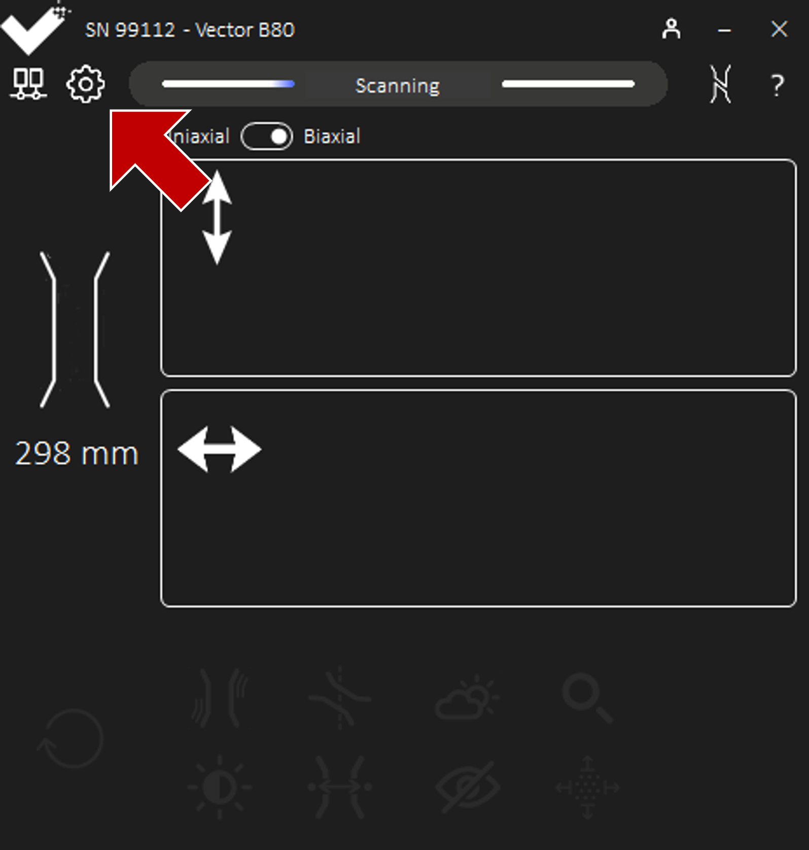
Power-on Vector and ensure Vector is Scanning.
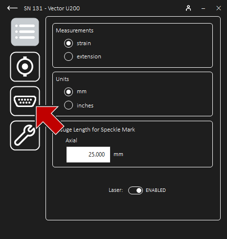
Once connected to Vector, navigate to Settings and then Digital Output to configure the output.
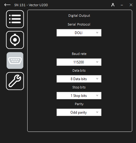
Set up the connection and select the Doli protocol from the drop-down list.
Parameter
Recommended Setting
Baud rate
115,200 (maximum)
Data bits
8
Stop bits
1
Parity
Odd
Doli Controller
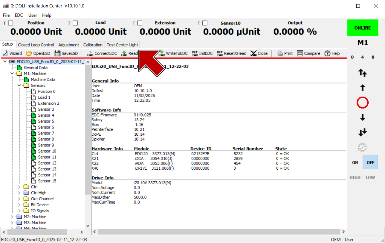
Launch the DOLI Hardware Installation Centre.
Select the controller and connect.
Once launched, the program should show the controller Online with the system tree on the left-hand side.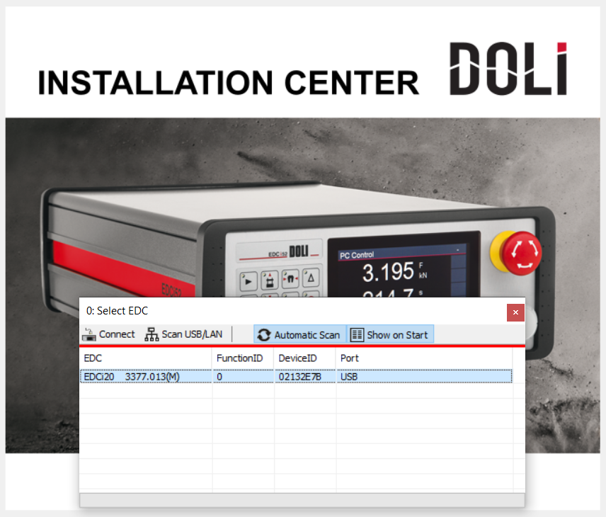
Allocate the required sensors in the system tree.
Select the first machine configuration, M1, and note the list of available sensors. A serial bus is a sensor.The Vector will output both the strain and extension for each measurement over the serial protocol. Two sensors are required for uniaxial, four sensors are required for biaxial.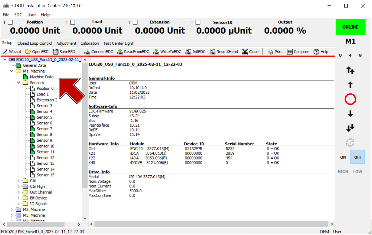
In sensor configuration, assign the first measurement output to the first sensor connector.
 Each of the required Vector measurement outputs have the corresponding channel ID as follows:
Vector Output
Y1 Port Connector ID
Axial Strain
X62A (SerSen 1)
Axial Extension
X62B (SerSen 2)
Transverse Strain
X62C (SerSen 3)
Transverse Extension
X62D (SerSen 4)
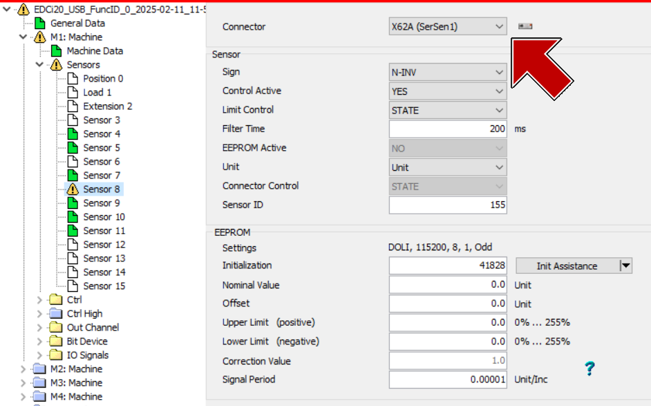
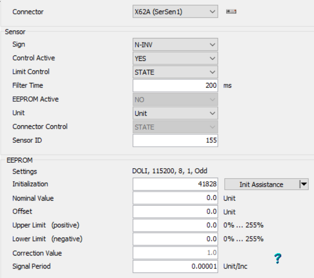
For example, set sensor #8 connector to X62A (SerSen 1) to allocate this sensor to Vector Axial Strain.In sensor configuration, assign the sensor parameters for the first sensor input.
 Each of the parameters should be set as follows:
Parameter
Value
Sign
N-INV “Non-inverting”
Control Active
Yes
Limit Control
STATE
Filter Time (ms)
200 (minimum)
EEPROM
NO
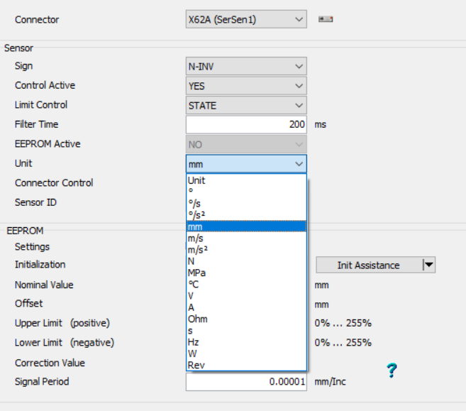
Unit
For Strain: Unit.For Extension: mm or inch as required.Sensor ID
(label as required)
In sensor configuration, EEPROM, match the protocol parameters to Vector for the first sensor input.
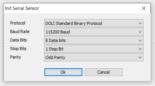
Open the Initialisation Assistant and click Serial Sensor.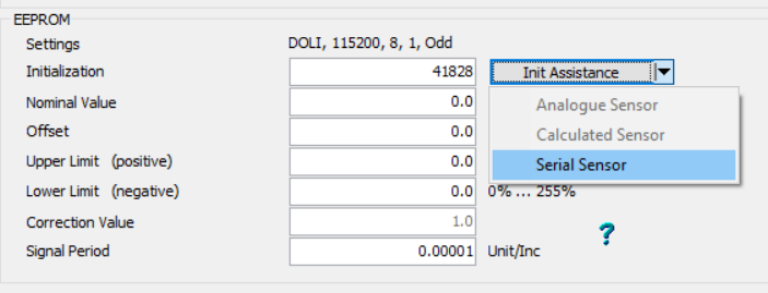 Configure each of the parameters as follows. Ensure they match the settings in Vector.
Parameter
Value
Protocol
DOLI Standard Binary Protocol
Baud rate
115,200 (maximum)
Data bits
8
Stop bits
1
Parity
Odd
In sensor configuration, EEPROM, assign the remaining sensor parameters for the first sensor input.
 Each of the parameters should be set as follows:
Parameter
Value
Nominal
0
Offset
0
Upper limit (%)
0
Lower limit (%)
0
Signal Period
000 01
Ensure the Signal Period is correct for the intended unit scaling. For example, with a strain sensor:A Signal Period of 0. 000 01 produces units in percent strain, and
A Signal Period of 0. 000 000 1 produces units in strain.
Repeat for all required sensors.
Repeat steps 4 to 8 for the remaining strain and extension channels.For example, set sensor #9 connector to X62B (SerSen 2) to allocate this sensor to Vector Axial Extension.Write to EDC and Confirm.
Each sensor that is written will require a reinitialisation.Unwritten sensors and machines are labelled with a warning icon in the system tree.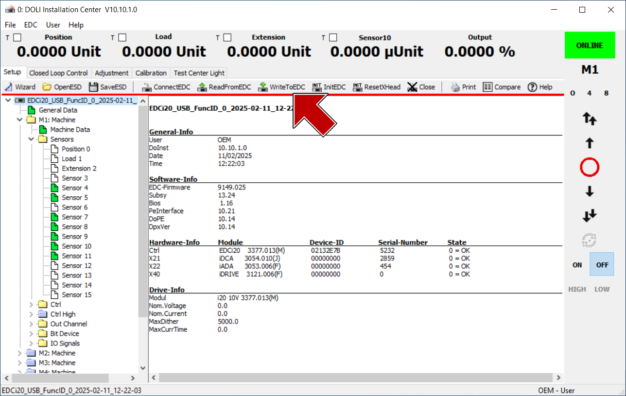
Test to Confirm Correct Setup.
Navigate to Test Centre Light.
b. Mark, Align, and Measure a specimen with the Vector. | Note: for convenince, a split specimen could be used.
c. Drive the specimen to a small strain or extension to observe a reading on the Vector Interface app. | Check each input sensor in DOLI Test Centre Light against the corresponding value on the Vector Interface.
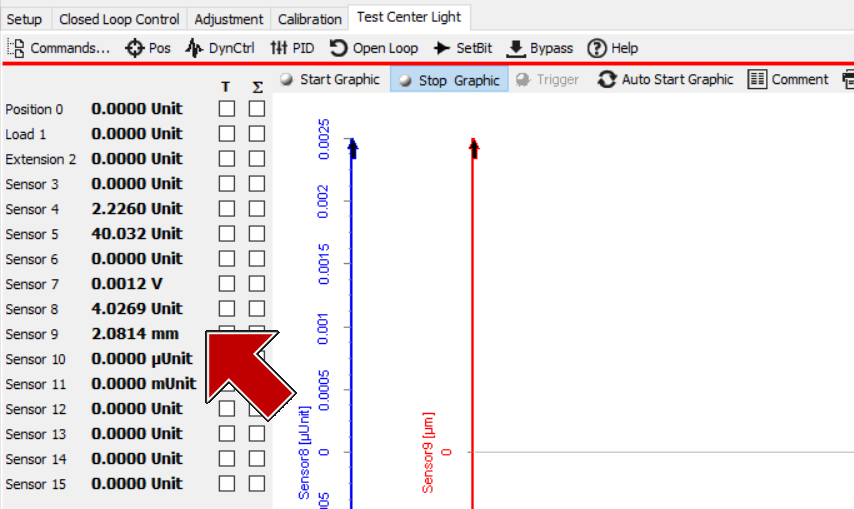 For example, when driving the UTM to strain a specimen to ~4%, sensors #8 and #9 match precisely to the corresponding axial values in the Vector Interface app.