Technical Guide - Tinius Olsen Digital Protocol
Hardware Set-up
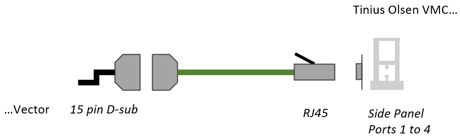
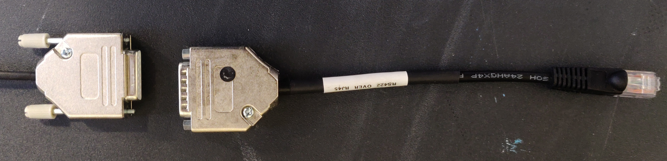
Connect the male 15 pin D-sub to the the female D-sub tail of the Vector Combined Power and Data Cable.
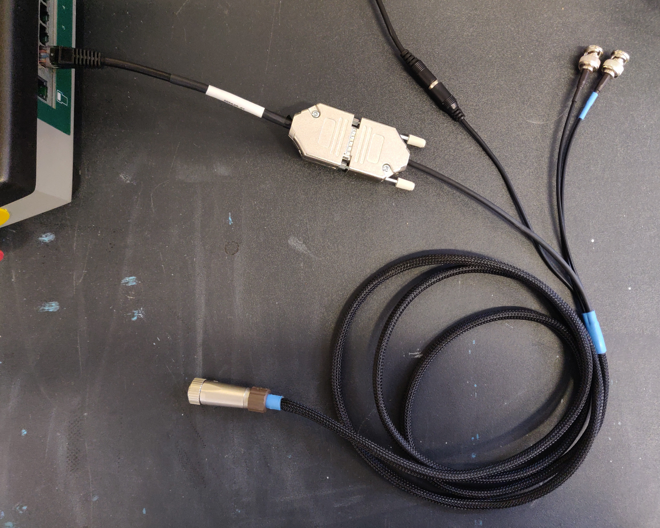
Connect the male RJ45 to an available port on the UTM panel.
Power-on the UTM.
Vector Interface Configuration
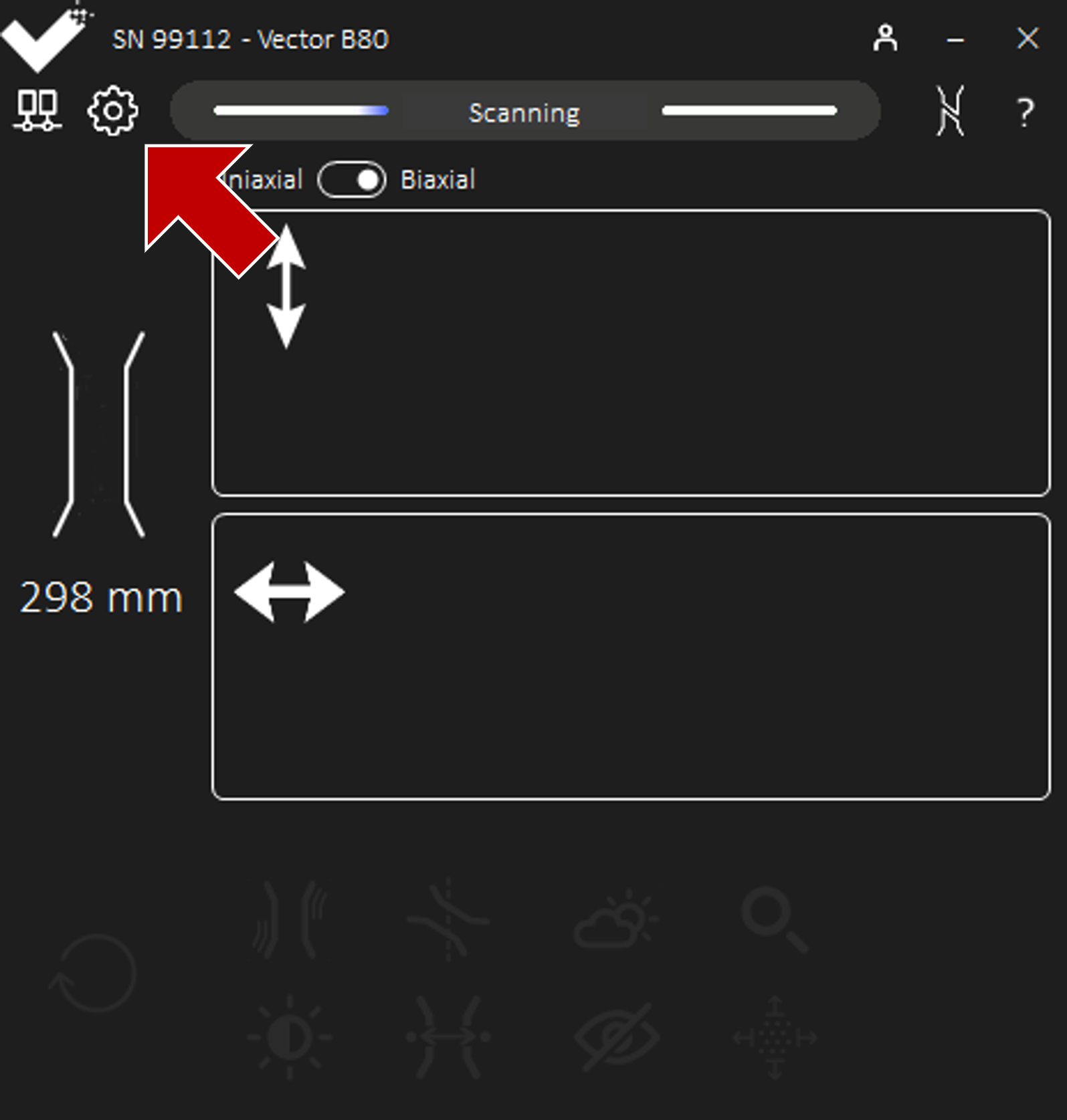
Power-on Vector and ensure Vector is Scanning.
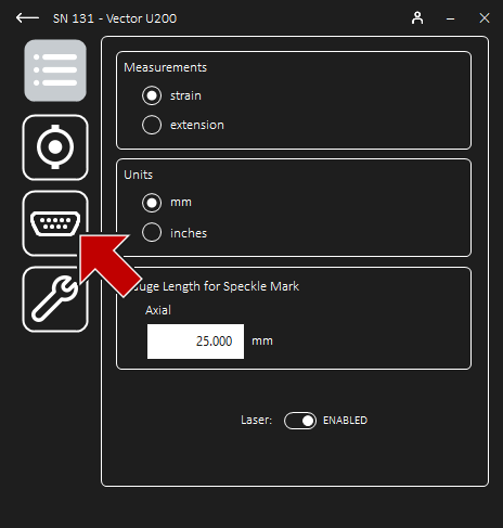
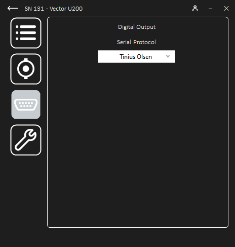
Once connected to Vector, navigate to Settings and then Digital Output to configure the output.
Select the Tinius Olsen protocol from the drop-down list.
Horizon Configuration
Stand-alone Configuration
Launch Horizon and VMC
Note: Digital protocol support from at least:Horizon version 10.4.0.0
ST frame FW version 1.18.06
Navigate to Configuration - Machine Set-up.
If required, refresh the connection to the desired UTM by clicking Test Connection or Refresh.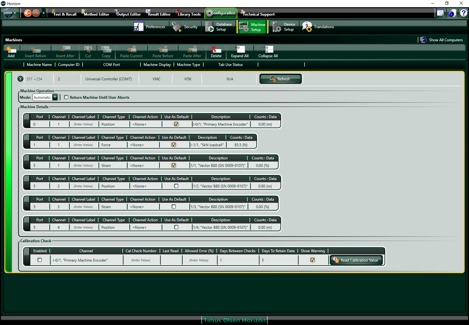
Check the available digital channels are listed as sources in Machine Details.
Each digital channel Description lists the Vector varient and the serial number, preceded by an identifier.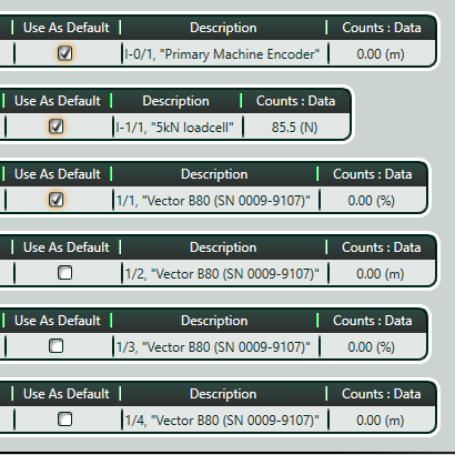 The identifier signifies the measurement from Vector as below:
Vector Output
Channel Identifier
Axial Strain
1/1
Axial Extension
1/2
Transverse Strain
1/3
Transverse Extension
1/4
Label each channel for reference.Note the Vector measurements correspond to the Channel ID’s, Channel Type’s, and Count Unit’s in the Machine Details.In the example here, Vector is providing strain, but the same approach is taken for extension or deflection: select the required channel for the corresponding source.Select the primary sources as default, if required.
Untick all sources that are not to be used as the default source for that type.For example, in the set-up:only the Machine Encoder is the default Position source,
only the Load Cell is the default Force source, and
only Vector Axial Strain (1/1) is the default Strain source.
In this way, the digital Axial Strain source will be automatically allocated to Strain for any standard method already in use.Navigate to Method Editor - Source Selection.
Select the required Method from the drop-down.Open the Source for Strain.
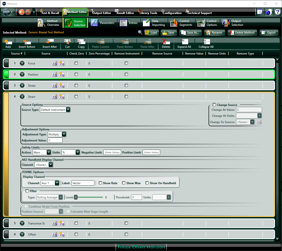
Ensure the Source Type is the Default Instrument
It may be useful to Label the source to display in the VMC under VMC Options.Set the Channel to Aux 1 and label appropriately.Open the Source for Transverse Strain, if required.
A new source may need to be created. Follow guidance from Tinius Olsen.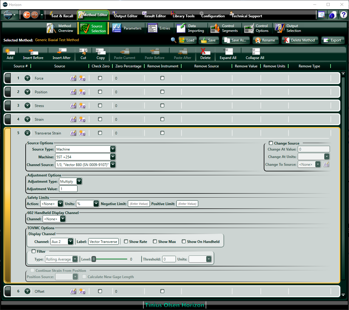
Set the Source Type to the specific Machine and Channel Source.
For transver strain, the Channel Source is 1/3It may be useful to Label the source to display in the VMC under VMC Options.Set the Channel to Aux 2 and label appropriately.
Integrated Configuration
Launch Horizon and VMC
Note: Digital protocol support from at least:Horizon version 10.3.1.10
ST frame FW version 1.18.06
Navigate to Configuration - Machine Set-up.
If required, refresh the connection to the desired UTM by clicking Test Connection or Refresh.
Check the available digital channels are listed as sources in Machine Details.
Each digital channel Description lists the Vector varient and the serial number, preceded by an identifier.
The identifier signifies the measurement from Vector as below:Vector Output
Channel Identifier
Axial Strain
1/1
Axial Extension
1/2
Transverse Strain
1/3
Transverse Extension
1/4
Navigate to Configuration - Device Set-up - Video Extensometer.
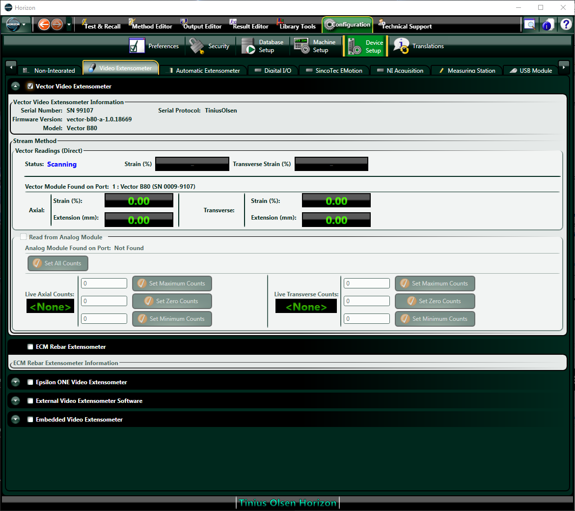
Tick the box for Vector Video Extensometer.
The connection will take a few seconds.The window display the connected Vector, key information, the status, and the values of each measurement.Ensure the connection is configured as Direct Digital protocol. If not, return to the Vector Interface App and configure the Tinius Olsen protocol for Vector. The test frame will beep to confirm a successful connection.Navigate to Method Editor - Source Selection.
Select the required Method from the drop-down.
Open the Source for Strain.
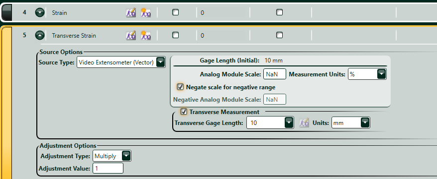
Ensure the Source Type is the Video Extensometer (Vector)
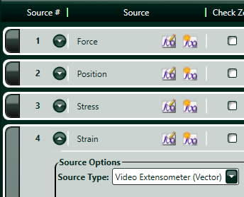 In the example here, Vector is providing strain, but the same approach is taken for extension or deflection: select the required channel for the corresponding source.
Configure the Source following guidance from Tinius Olsen.
Displayed settings relating to analogue scaling can be ignored as they will not apply when using digital. Scaling of digital protocol is not required.Repeat as required for Transverse Strain.
A new source may need to be created. Follow guidance from Tinius Olsen.For transverse measurements, tick the box to define the source correctly automatically depending on the source type.