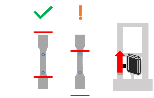
Lasers Not Aligned

|
|
Vector Lasers Not Aligned to Specimen

The Vector is positioned where the detected markings are outside the laser guides. Vector projects a laser arrangement for assisting alignment within the calibrated region when in Scanning mode.
Solutions
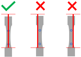
Reposition Vector so that the central laser intersects the specimen markings.
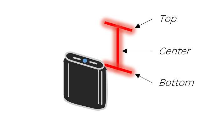
The central vertical laser represents the axis of movement. Ensure it is aligned to the specimen markings.
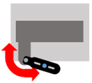
Vector’s position can be easily adjusted by loosening the mounting points via the levers and guiding Vector to a new position. Adjust the position of Vector using the intermediary, UTM stub axle, and extension arm if used.
Raise or lower Vector so that the markings are between the top and bottom lasers.
The top and bottom lasers represent the extent of module. Ensure that the top laser is above the markings.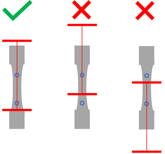
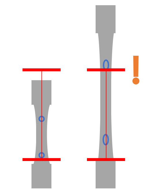
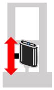 Adjust the position of Vector using the UTM rail, by relocating the intermediary, or by attaching the UTM rail to the UTM at a higher or lower position. See Positioning Vector for more information.When aligning, take care that the range of motion of the specimen during the test will fit within the top and bottom lasers.
Information

The Vector intermediary can be fastened at three different heights on either side of the extensometer
Information

After moving the module or specimen, wait a few seconds for warning indicators to settle.
Vector Aligned Too Low
Vector is positioned with markings within the top and bottom lasers, but not to the location of best-practice.
Solutions

Information

The Vector intermediary can be fastened at three different heights on either side of the extensometer
